Lets implement a rising edge detection in Verilog for a PSoC4.
Yes I know that there already is a edge detection component, that this is a overkill and can be done way easier but this is just a very simple example. Also I don’t dig too deep into the technology behind as it is simply too complicated. If you want to dig deeper, check the “Component Author Guide” you’ll find in the Help Section of “PSoC Creator”
We start “PSoC Creator” and create a new Project, as I want to do it for a PSoC4 I select an empty workspace with my device. The component will be generic so it doesn’t matter which device or family you choose.
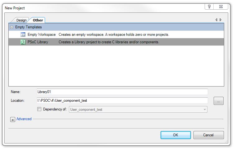
Next we create a new Library for the component, this way the component easily can be reused, create the Library:
- File->New->Project
- Select the “Other” Tab
- Select “PSoC Library
- Give it a name, such as “my_components
- click “OK”
In the Workspace Explorer you select the “Components” Tab, here you can find an overview of all components created.
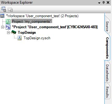
Right click on “my_components” and on “Add Component Item”
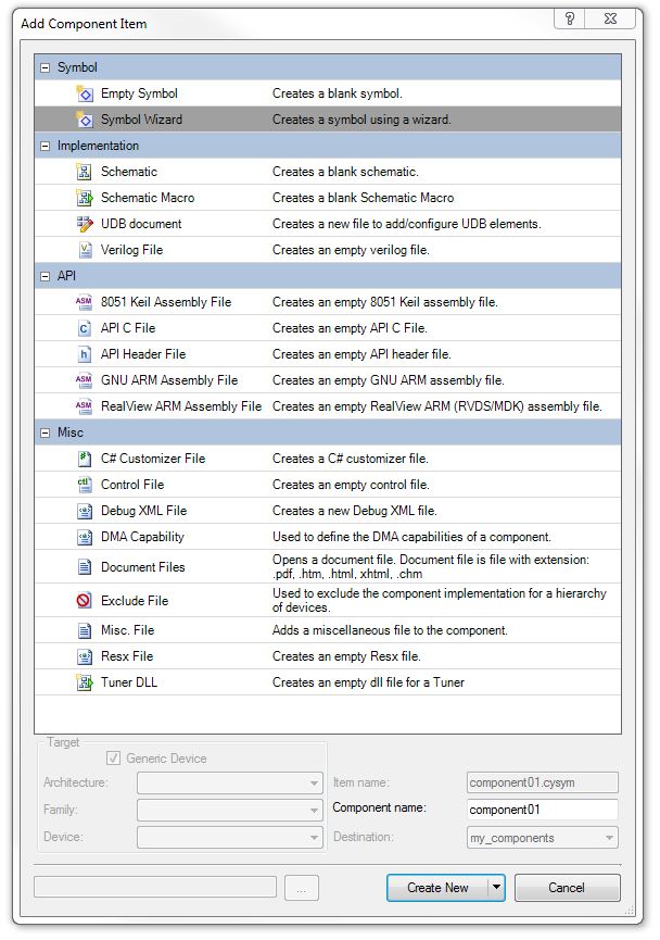
Those are the items you can add and those are the items out of which the component is “constructed”. The Symbol is the symbol the you see when you drag the component into the schematic. “Implementation” are the files that can be used to describe the behaviour of the component. The files in “API” are used to set up the API of the component which later can be used to pass parameters or get data out of the component. The files below “Misc” should be self explaining, you can create own configuration dialogs and add documentation files for you component.
We start by Starting the Symbol Wizard, note that we have to give a component name on the bottom, I choose “edge_detection”.
In the wizard now we can set up the connections for our component, I want to have an input (d) a clock and a output (q), also I change the tile color as it is purely digital.
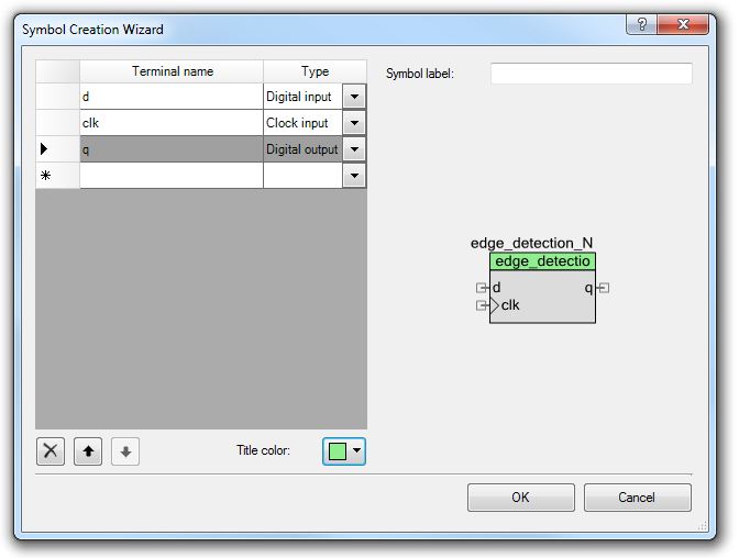
After clicking “OK” you will have the symbol on an own canvas. You can use this canvas to modify the symbol, all the wizard does is to set up the connections of the symbol.
By right clicking on the canvas next to the symbol we can select “Symbol Parameters”
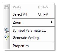
Those are the parameters of the symbol, which are divided into “formals” which can be accessed by the user and “Locals” which are just internal parameters, click “OK” to close that window.
Now we again right click next to the symbol and select “Generate Verilog”. Note the checkbox “Generic Device” which means that this component is for all PSoCs that use “PSoC Creator”. Click “Generate”.
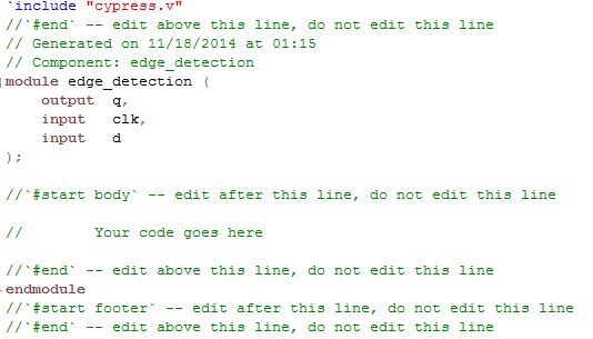
Next we see that a Verilog file was created with a module header. We now simply need to add the code:
If you want to learn more about State Machines, check the page.
The file with the source for the edge detection (mealy machine).

Save the file.
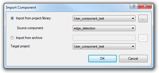
In the “Components” Tab of the Workspace Explorer right click on the PSoC4 Project we have created in the very beginning and select “Import Component”, we now can import our component into the project for the device.
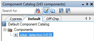
We go back to “sources” on the Workspace Explorer and double click the “TopDesign.cysch” of the PSoC Project., on the right side in the “component catalog” we now have a new tab with our component.
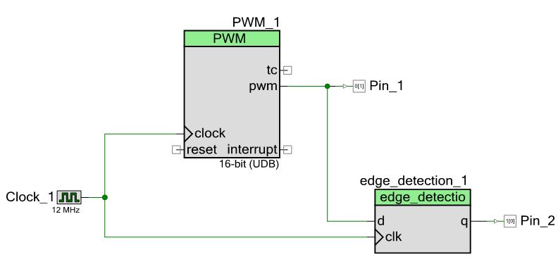
I have added this component to my main schematic, together with a small testbench to test the functionality using a logic-analyzer.
We now can compile the project.
You might want to check the “Results” Tab of the Workspace Explorer. There you will find reports about the usage of UDBs (where the logic is going) in the *.rpt file as well as timing informations in the *_timing.hml.
I have used a logic analyzer to check if the component is working like it should:
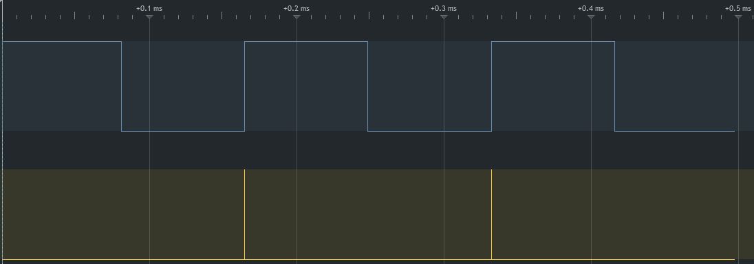
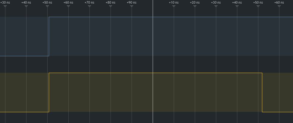
which is what we awaited, if we have a closer look
1 thought on “Own PSoC Components in Verilog”