I received the new bluetooth low energy pioneer kit from cypress and want to write a bit about what it is and how to get started with it.
The chips in this kit are designed to make the Internet of things (IoT) happen by connecting everything to everything. An example is your dishwasher which is telling your smartphone that its done or the smartwatch telling the heater to reduce the temperature while you are not at home. BLE is taregting for communication over short ranges, for example so called wearables (devices you af close to your body,like smart wrist bands or smart shoes).
So why is this kit so interesting to me?
It features the new PSoC4BLE chip. BLE is for Bluetooth low energy which makes it possible to drive those chips with a coin cell only for a long time. The chip consumes 1.3µA at deep sleep, 150nA in hibernate and 60nA in stopmode (source). The way more interesting point for me is, that this is a single chip solution on a programmable SoC. PSoC makes it possible to configure the hardware the way you want it. You need few PWMs for your project? Drag and drop them into the workspace. You need few UARTs instead, just drop them. There are tons of ready modules but you can also write own ones as I did here. Now there is even a bluetooth module, you will need an an antenna, an oscillator, 2 caps and a inductance.
Also there is no need for bitbanging in registers as every module will generate a well documented API. Those APIs tended to be a bit buggy but this really has changed and with the new PSoC Creator IDE it is really working well.
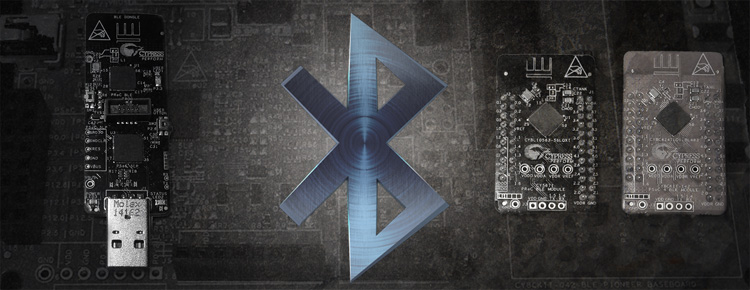
What’s inside the Kit?
When opening the box you get not 1 but 4 PCBs.
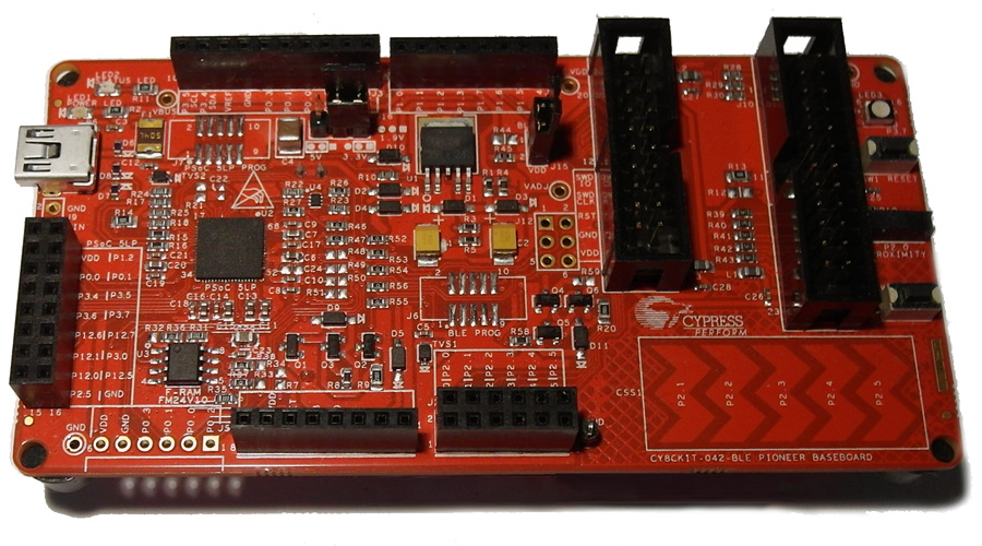
CY8KIT-042-BLE Pioneer basebaord
While on the PSoC4 Pioneer kit the actual chip was soldered directly on the PCB, they now made it changeable. This way you can change the device you work with while the board is providing the programmer and debugger. The chip handling the programming and debugging is a PSoC5LP. Cypress has released the sources for this chip so basically you can build up your own kit. Besides the programmer there are voltage regulators, arduino compatible pin headers, capsense fields, a RGB LED, a proximity sensor and a button onboard. Besides that there is also a non-versatile F-RAM FM24V10 which can be accessed from the Module Header, I don’t know what exactly this is for but I guess its for low power applications to hold data so the internal RAM can be deactivated while the device is in a power saving mode. The F-RAM is accessed via I²C

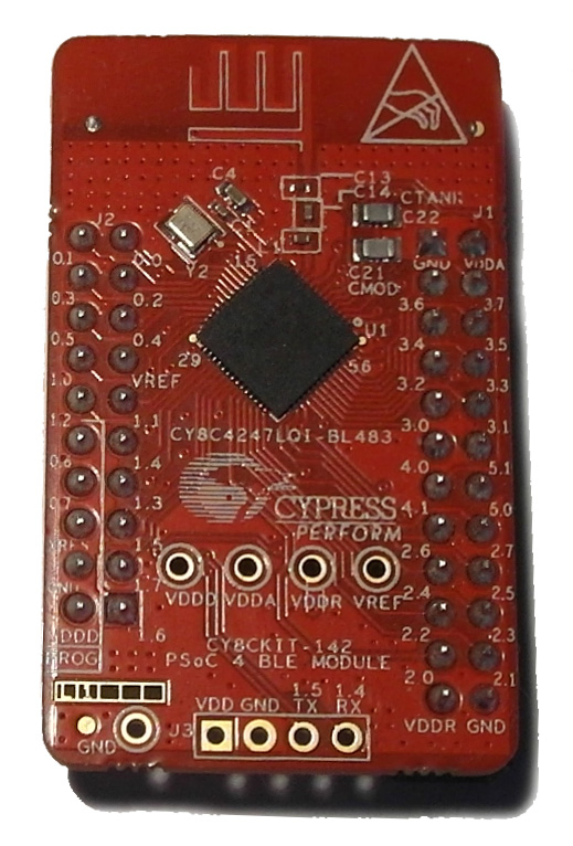
CY8CKIT-142
I really like the concept of the changeable chips. This is not because I can test different chips (which is cool though) but this way the PSoC 4 can find its way into hobbyist projects. None of the PSoC Creator compatible Chips comes in a DIP. I don’t want to design an own PCB to have easy access to pins in hobby projects. The PSoC4 prototyping kit was already a step in the right direction but the programming and the lack of onboard debugging was a problem to me. To be honest, the arrangement of the Pins on the PSoC4 Pioneer kit is a pain! The worst part is that some pins are not even available! Try to connect and SCB SPI to the Kit. That is a very big minus for me, good thing there is now this solution!
The chip on this board is a CY8C4247LQI-BL483. The 4200 BLE Series is a 48MHz ARM Coretex-M0 with up to 256k flash and 32k SRAM. Four Opamps, 1Msps SAR ADC, Capsense, Bluetooth, 36GPIOs and of course the custom peripherals (source)
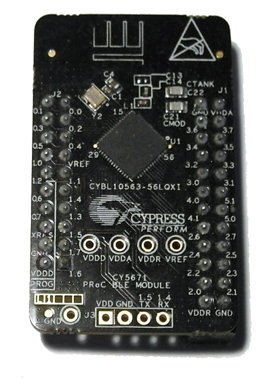
CY5671 PRoC BLE module
This guy is new to me. The chip is a CYBL10563-56LQXI. PRoC is for Programmable Radio-on-Chip. From what I discovered so far, the main difference to the PSoC Chips is that there are no programmable logic blocks. So this is an classical microcontroller with in built Bluetooth. The other specs are similar to the 4200 BLE Series with less analog capabilities. Well, I don’t think that I will use this module too much but I will give it a try at some point.
CY5670 – CySmart USB Dongle (BLE Dongle)
Also I don’t know that product. The website says that this dongle can be used for testing and debugging of BLE peripherals. It has own software which is called CySmart. After a firmware update of the device I can run it.

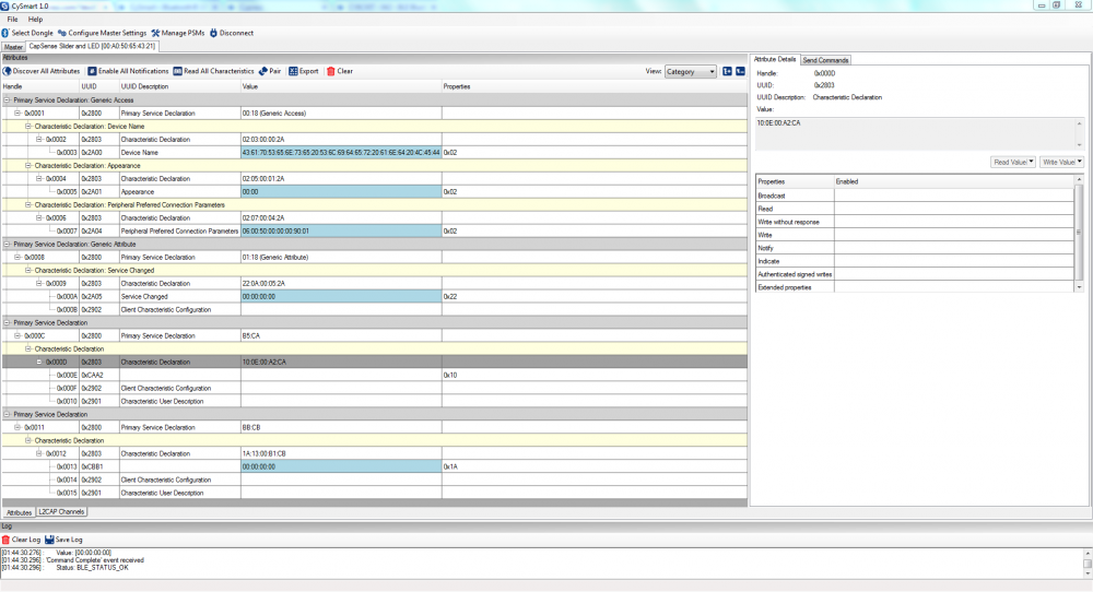
As you can see, it is showing the technical details of the connected device, this is great for debugging. There is one thing I don’t like about the dongle. The buttons are hard to use, they are sideways and its hard to push them.
Beside the CySmart Windows Software there is a CySmart App for smartphones.
This app can be used to control the RGB LED and to get the information from the CapSense Slider if you have the default firmware running on the CY8CKIT-142.
The first touch
There are a few sample Projects available
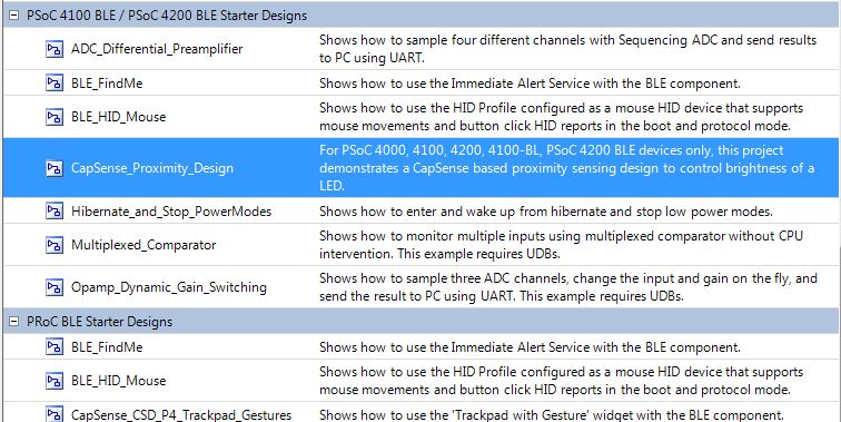
So I take the Capsense Project without BLE to check if there are any differences to a regular PSoC4 Project. After I have relocated the PWM to the right Pin it works, if my finger gets close to the sensor it brightens up. Not too spectacular, also because I once pushed capsense to the limits when building my capacitive joystick.
Lets test a sample with BLE. I choose the HID (Human Interface Device) Project which is demonstrating the use as Bluetooth mouse. Before having a look at the configurations and the source I flash it and see what it is doing. I now can use CySmart (either on the PC or the app) to get information about the services the device is offering. Of course I can see a HID Service there but also a Battery Service which is offering information about the Battery Status.
I also can use my Android Smartphone to connect to the “BLE Mouse”. If I do so, I see a cursor moving around, if I press the button on the board it does a click on the smartphone. Thats cool!
So lets see how this works.
First I check the BLE module configuration
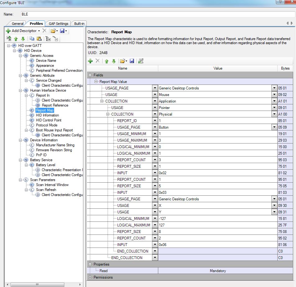
Well, that looks familiar. Looks like USB! I don’t want to dig too deep into all the options as this is out of scope for this post.
Also the next tab is interesting:
The code is a bit bloated as there is a lot of debug information stuff and they tried to make it low power, but lets have a look at the “SimulateMouse” Method as there should be some magic going on. The most interesting part here is:
CyBle_HidssSendNotification(cyBle_connHandle, CYBLE_HUMAN_INTERFACE_DEVICE_SERVICE_INDEX, CYBLE_HIDS_BOOT_MOUSE_IN_REP, MOUSE_DATA_LEN, abMouseData);
So basically we have the connection, an index if you use multiple devices, the index of the service characteristics, the length and the actual mouse data in form of an array with 2 axis. With “CyBle_ProcessEvents” this data is processed and send to the client.
But before trying to understand that sample in detail, I build my own project from scratch to get a deeper understanding.
Walk through the given tutorial
Cypress is giving providing a getting started which is … confusing… not because its not explained well, but due to the complexity of BLE. If you want to learn about BLE this getting started is a good starting point. I will just shortly rush through this, to give an idea how it is set up, if you want to rebuild it check the document of Cypress.
Basically BLE is build up from several layers:
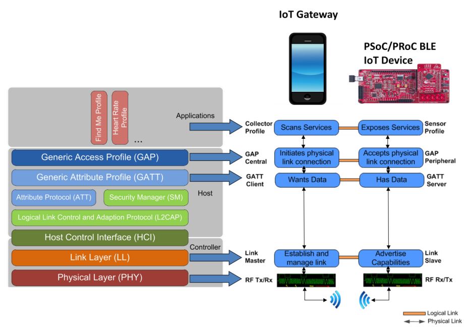
Where you can use pre-defined profiles for your application or set up custom ones.
In the getting started you will build a “Find Me” Device which can wake up from an event and starts controlling an LED. Blinking LEDs, the “Hello World” of embedded 😉
First we need a profile:
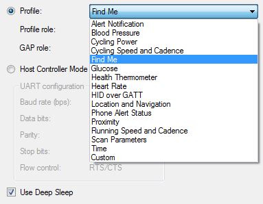
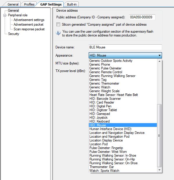
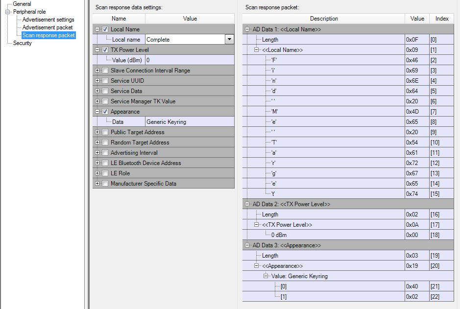
Next you have to define more specific parameters, like a timeout for advertising (how long the device will be visible to others) and also the Name and Type of the device that is advertised. You have to define which information should be advertised and which should be in the response of a scan.
In the getting started you next have to add an PWM. This is nothing special but I have to mention the beautiful GUI. Look at that:

Same for the Pins, beauty!

We add a few Pins and adjust the clock. Then we are done with the hardware already.
Next is the Firmware, in the document you will find flowcharts etc, this is just a wrap up.
The tutorial starts with:
    CYBLE_API_RESULT_T apiResult;
    CyGlobalIntEnable;
    PWM_Start();
    apiResult = CyBle_Start(StackEventHandler);

    if(apiResult != CYBLE_ERROR_OK)
    {
        /* BLE stack initialization failed, check your configuration */
        CYASSERT(0);
    }
    CyBle_IasRegisterAttrCallback(IasEventHandler);
Which means we have an enum which will tell us the status of the device.
We enable global Interrupts and start the PWM (all peripherals need to be started by software if no explicit start by HW is defined)
The BLE module is started with an eventhandler given, any event that has to do with the stack (like disconnect, connect, timeout) will be handled there.
We check if the BLE started with any errors by checking the return value of “CyBle_Start” (why don’t move this directly to the if-condition?)
If we have an error, a macro is called which will halt the device.
Next we register the eventhandler for Bluetooth Events.
After this init part we enter the main loop:
    for(;;)
    {
        CYBLE_STATE_T bleState;

        /* Single API call to service all the BLE stack events. Must be
        * called at least once in a BLE connection interval */
        CyBle_ProcessEvents();

        bleState = CyBle_GetState();
        if(bleState != CYBLE_STATE_STOPPED && bleState != CYBLE_STATE_INITIALIZING)
        {
            /* Configure BLESS in DeepSleep mode */
            CyBle_EnterLPM(CYBLE_BLESS_DEEPSLEEP);

            /* Configure PSoC 4 BLE system in sleep mode */
            CySysPmSleep();

            /* BLE link layer timing interrupt will wake up the system */
        }
    }
the job of it is basically to check if all events have been processed and if the sleep mode can be entered.
Lets have a look at the 2 eventhandlers:
void StackEventHandler(uint32 event, void* eventParam)
{
    switch(event)
    {
        case CYBLE_EVT_STACK_ON:
        case CYBLE_EVT_GAP_DEVICE_DISCONNECTED:
        /* Start BLE fast advertisement for 30 seconds and update link
        * status on LED */
        CyBle_GappStartAdvertisement(CYBLE_ADVERTISING_FAST);
        Advertising_LED_Write(LED_ON);
        PWM_WriteCompare(LED_NO_ALERT);
        break;

        case CYBLE_EVT_GAP_DEVICE_CONNECTED:
        /* BLE link is established */
        Advertising_LED_Write(LED_OFF);
        break;
        case CYBLE_EVT_TIMEOUT:
        if(*(uint8 *) eventParam == CYBLE_GAP_ADV_MODE_TO)
        {
            /* Advertisement event timed out, go to low power
            * mode (Hibernate mode) and wait for an external
            * user event to wake up (reset) the device again */
            Advertising_LED_Write(LED_OFF);
            Hibernate_LED_Write(LED_ON);
            PWM_Stop();
            Wakeup_SW_ClearInterrupt();
            Wakeup_Interrupt_ClearPending();
            Wakeup_Interrupt_Start();
            CySysPmHibernate();
            /* Code execution never reaches here, wakeup from hibernate
            * is through device reset */
        }
        break;

        default:
        break;
    }
}
This is the event handler for stack events. you can see that will start advertising as soon as a device disconnects. As soon as a device connects it stops advertising and if there is a timeout it will go into hibernation mode and arm the interrupt from the pin. As soon as we have an interrupt on the pin, the device resets.
Next is the, if you will, command handler.
void IasEventHandler(uint32 event, void* eventParam)
{
    /* Alert Level Characteristic write event */
    if(event == CYBLE_EVT_IASS_WRITE_CHAR_CMD)
    {
        uint8 alertLevel;

        /* Data structure that is returned as eventParam */
        CYBLE_IAS_CHAR_VALUE_T *charValue = (CYBLE_IAS_CHAR_VALUE_T *)eventParam;

        /* Extract Alert Level value from the data structure */
        alertLevel = *((charValue->value->val));

        switch(alertLevel)
        {
            case NO_ALERT:
            PWM_WriteCompare(LED_NO_ALERT);
            break;
            case MILD_ALERT:
            PWM_WriteCompare(LED_MILD_ALERT);
            break;
            case HIGH_ALERT:
            PWM_WriteCompare(LED_HIGH_ALERT);
            break;
            default:
            break;
        }
    }
}
It extracts the alert level from the event parameter and sets the PWM compare value. A value between min and max of the PWM will make the LED blink while 0 will turn it off and PWM-max will turn it on permanently.
Testing it
Ok, so now that we have everything together we go for a first test.
After reset, the device goes into advertising mode, indicated by “green” on the RGB LED. I’m able to connect to the device with my smartphone. If I don’t do so, the advertising timed out after 30 seconds and the RGB LED turned “violet”. After it has reached that state I can wake up the device by pressing the button on the board. After a short initialization (PWM LED is on while advertising is off) the device goes back into advertising mode “green”.
On my smartphone I see this:
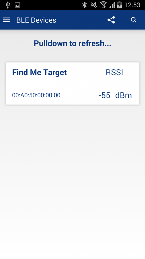
hey, this looks familiar…
Once connected I see the following:
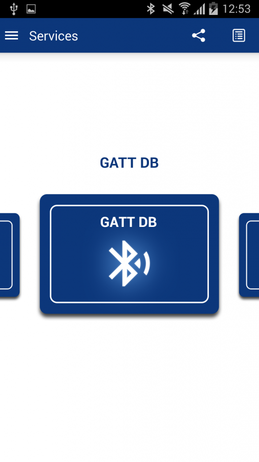
So the Find-Me Profile is also implemented in the App.
First lets have a look at the GATT where we can find the Immediate alert. (which seems to be the only data-field in this profile)

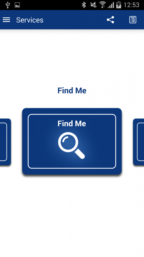
Finally the Find-Me
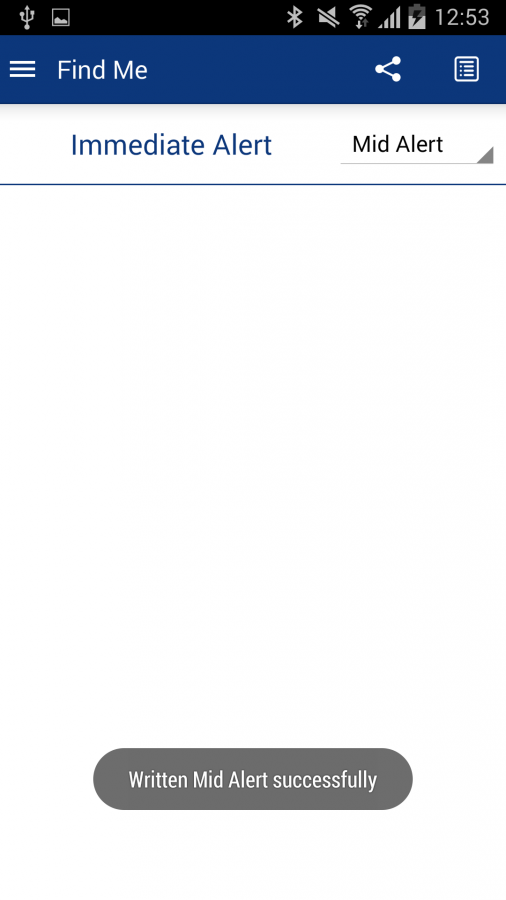
where we can set the alarm level and control the LED.