I have the idea to build a unmanned aerial vehicle (UAV) which I can control using the computer while it is flying somewhere. I do know about airplane mechanics and a bit about avionic but I don’t have practical experience with aerodynamics or how to fly a R/C plane I decided to build a small plane to get in touch with the whole topic.
Building the plane
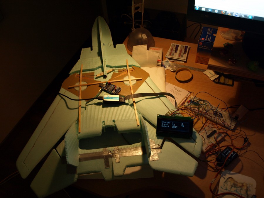
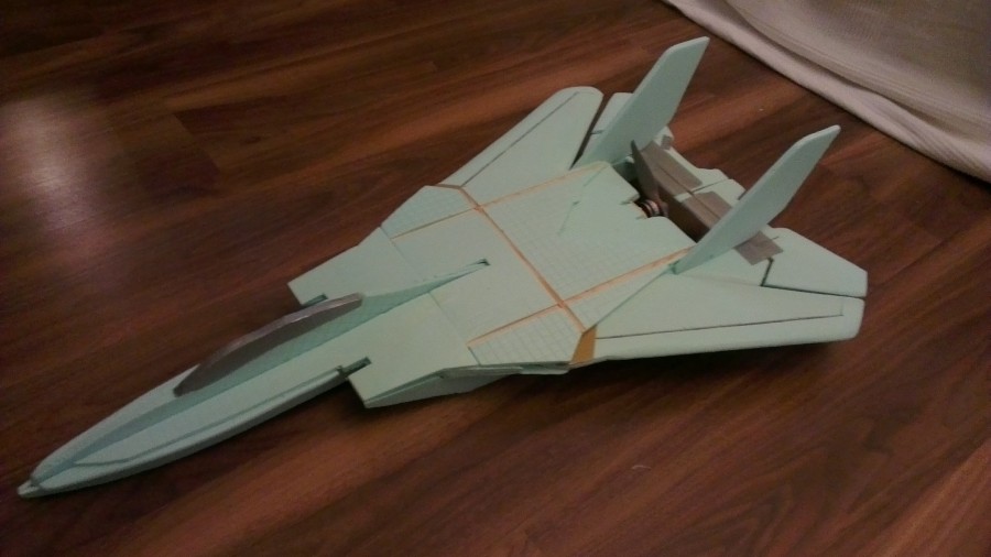
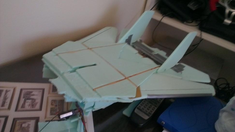
There are plans for Styrofoam planes (called foamies) on the web, you basically get a plan with the shape of the plane and that’s it. So you have to build everything from the scratch. My Idea was to build one of those planes (F14) and equip it with some microcontroller stuff. A F14 is not really a good choice to start RC flying because it is hard to control and not self stabilizing but if I could manage to fly that plane the chance that I will make it to fly something less aggressive (but more expensive) is bigger. Also I am building a R/C PC-Interface to fly a simulator to get a feeling. The first challenge was to get proper material to build the plane. Usually 6mm Depron is used but it is expensive (5€/m²) so I decided to use impact sound insulation (4mm) which is cheaper (2€/m²) and to reinforce the material whenever needed. This setup gave me the advantage to make other parts thinner and therefore lighter. Unfortunately the insulation comes with a pattern so I had to sand the surface (at least wings etc.).
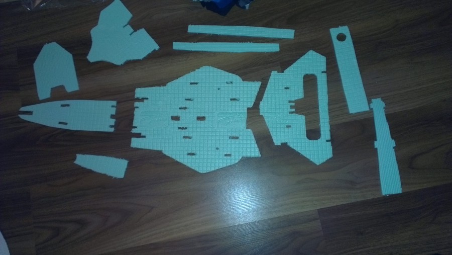
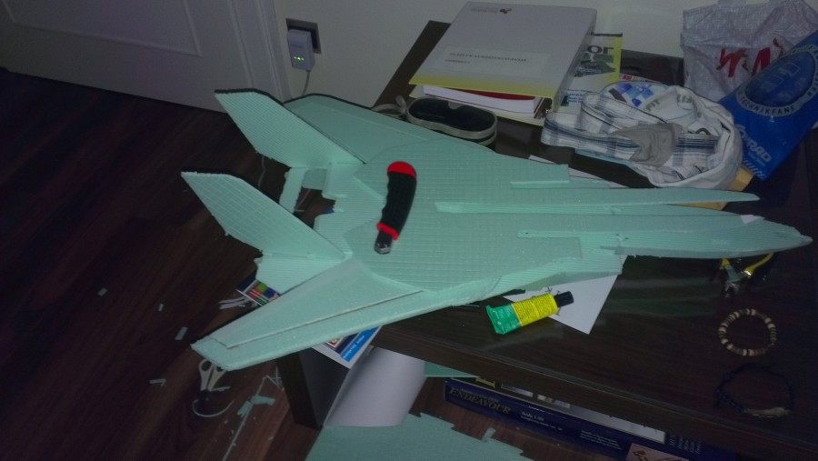
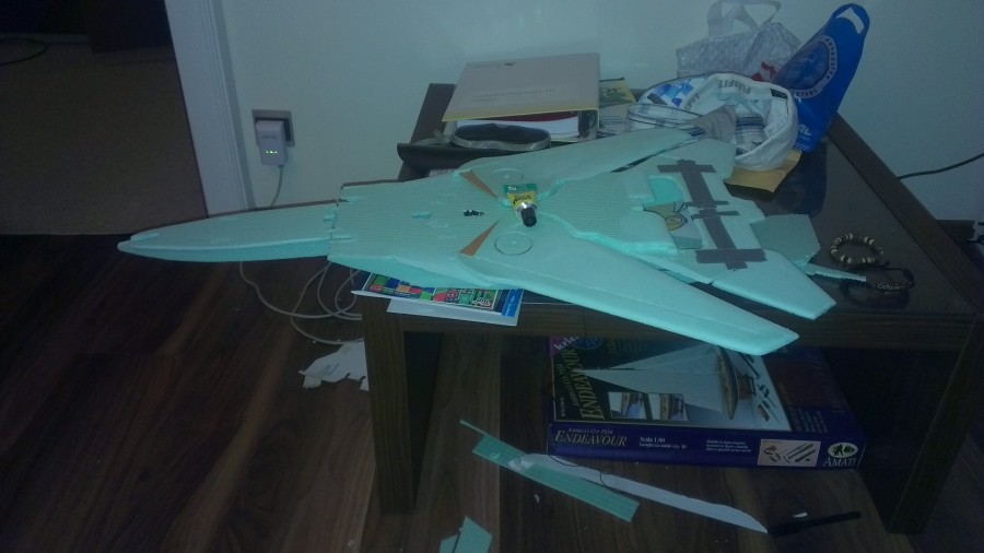
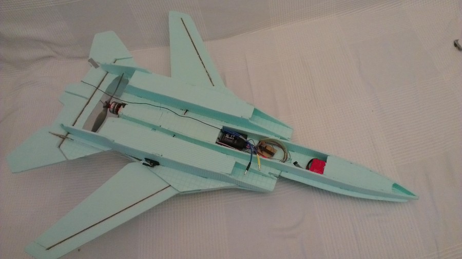
Usually carbon fiber tubes are used to reinforce the wings and other critical parts but as I wanted to make it as low cost as possible I used some wood which was left over. Also I had to reinforce the upper part since I wanted to make sure it is able to handle some stress if the plane crashes, the nose of the plane is just made of foam so it is damping an impact while it is destructed but is protecting the much more critical part in the middle of the plane (unfortunately I have the proof that this idea is working).
Electronics
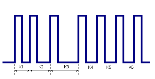
This plane is controlled with 2 servo motors for the Elevons and a brushless motor. I got the brushless motor with a electronic speed control (ESC, basically it is a DC/tri-phase AC converter) very cheap from china (15€). I owned an old FM 414 analogue RC system which I decided to use. The Problem with the servo Motors is that you have 1 channel to go up/down (Y) and 1 channel to roll (X). But the servo position is influenced by both channels as you can see in the picture below, this is called delta-mixing. There are modules for doing that but because I already had planed to use a microcontroller I decided to try make it on my own. So here comes some theory. Notice that one servo usually is mounted flipped, so the function for this servo would be -E .
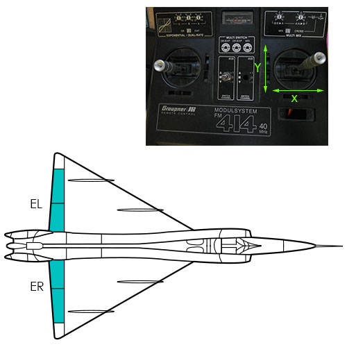 |
EL=-Y-X; ER=-Y+X
Here is a small video of how it looks like (new version with MX-12 and implemented delta mix) |
Now there are 2 options. Mixing it in the sender and sending a separated signal for each servo or mix in on the receiver side. As I planned to implement also other functionality, such as auto-stabilization, I decided to implement the mixing on the receiver side. To realize this I first need to digitalize the signals from the sender. But what do you get? The system the RC is based on is called PPM (puls – pause – modulation) which means that each channel is transferring a pulse. The length of each pulse indicates the position of servo/whatever. The total frame is fixed to 50Hz. The receiver splits the PPM signal and is just passing the pulse to the output port of the channel. This means that at this port you get a periodical pulse and the pulse width (1-2ms) is representing the value (PWM).
Ok, so far, so good. We need to somehow measure the length to make a digital value for each channel (in this case 2 channels) then do some calculations and then generate a new PWM to control the servo motors. There are different ways of doing it. I decided to work with a timer block and interrupts. If there is a rising edge on one of the channels I start the timer and at a falling edge I read the value. This is giving me the advantage that I only need one timer for as many channels as I want in one PPM. The problem is that the FM414 seems not to stick to the specification so the 2 channels did not really had a gab between the pulses as you can see below.
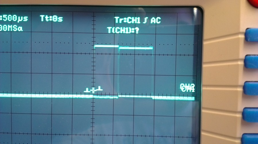
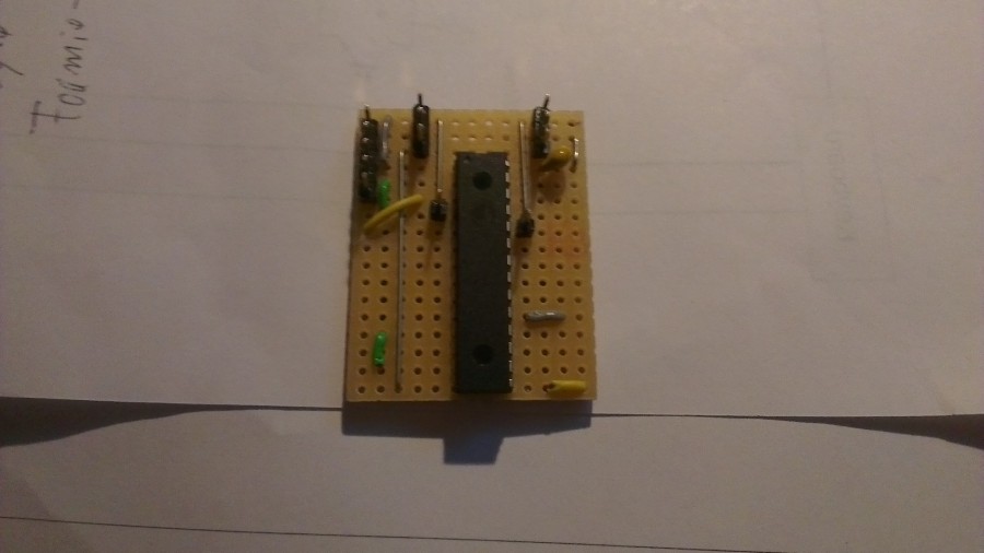
This could be solved by choosing 2 channels which are not next to each other or by using a separate timer for each channel. I decided to manage it somehow (just to prove myself). So I optimized the code until I made it to get the values. So I added the calculations the PWMs and some other things until I realized that the chip may not be able to handle everything and keep the timing correct. That was the reason why I decided to make a dedicated chip just for measuring and one for mixing the signals and generating the PWM. I am measuring the channels and send the values to another chip using UART. On the second chip the signals are mixed and the servos are controlled.
While configuring the elevons i realized that the signal quality was very bad even if sender and receiver are in the same room. But as the FM414 was the only sender I had, I continued developing on that platform until it was done.
Watch the test here (also the sweep wings ;)). After the system was working I tried to give it a try and fly. The control was way to aggressive. The nose of the plane was destroyed but it was easy to rebuild. I wrote an update for the firmware and finally I made it fly !!!
But my guess was right, as you can see in the video above, shortly before landing suddenly the plane climbs. This was not on purpose! I made it to make it fly but with the FM414 it will not work reliable. Therefore I bought a MX12 which is a 2.4GHz digital bidirectional controller. Also it is able to do the delta mix native.
I also mounted a small camera at the nose of the plane. I tried using accelerometers to realize a stability regulation and to keep the camera on the horizon as you can see here.
This is working perfect when the engine is not rotating but the sensors are not able to handle the vibration of the motor. I tried to filter the signal but I did not make it work reliable. So the camera is fixed 🙂 I’m sure it would work better with a better sensor/gyroscope. Anyway I want to show you 2 FPV videos, one is in Stierstadt/Germany, the other near Espoo/Finland
Conclusion
It was a lot of fun building the plane and also I learned a lot. With the MX12 it is working much more reliable. So I was flying it a couple of times until I got the proof that my energy absorbing nose is working.
Its nothing that could not be rebuild but I first want to focus a bit more on the FM414-PC convertion and on the software for the next generation plane. I will keep you up to date.