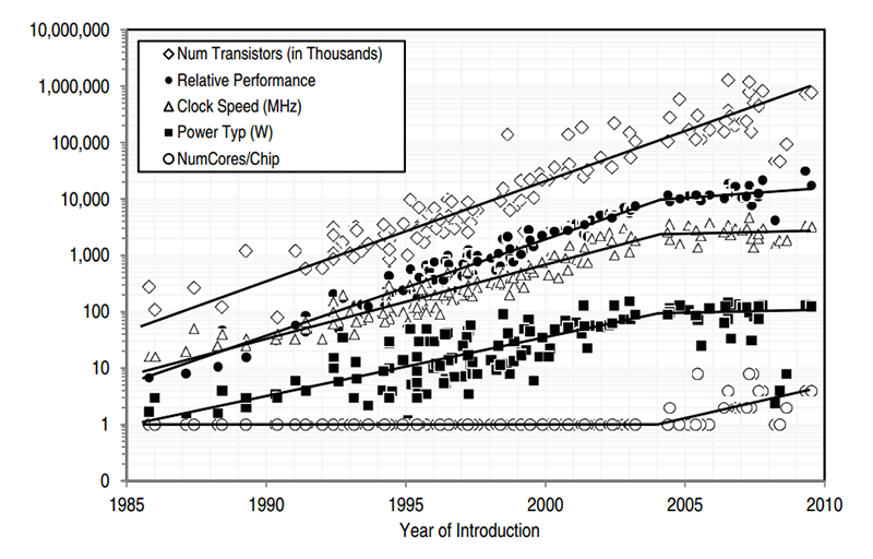
Since the 70’s, Moores Law was the driving force behind the increase of computing power. As we know, we start to reach the physical limitations of downscaling, which made higher frequencies possible but also lead to higher leakage currents and therefore power consumption and heat. As squeezing a lot more GHz out of the circuits might be not possible (at least for now), we know a strategy to increase computational speed at constant clock frequencies: parallelization.
Multicore CPUs (multiple CPUs/cores on one physical chip) are nowadays common in mobile devices such as smartphones and tablets as well as in desktop PCs and servers. Typically, with 2-8 cores while 16+ cores (so called many-core systems) will be the future. However, in embedded applications multicore architectures had been used e.g. for DSP tasks in communication applications, but they are not very common for generic tasks by now. Due to the demand of more complex applications (connected car, IoT etc.), multicore microcontrollers will be the future also for embedded applications. Also multicore microcontrollers might be very interesting for safety related applications as the redundant structures can be used to monitor each other and might lead to a lower probability of failure compared to a single core.
If you write software for a PC, you usually do not care about the architecture in the background as the operating system is handling most of the stuff for you. Embedded microcontrollers are different. When writing software for microcontrollers, you are a lot closer to the hardware (though this is changing). Very often the chip-manufacturer gives you nothing but a big ass manual with thousands of pages describing which register is doing what, the rest is up to you. Of course this is nothing a beginner would start with, but for others (like me) this is a lot of fun! Luckily we have systems like the Arduino or Cypress PSoCs where you can start hacking around with basic C/C++-knowledge.
I really want to encourage you to dig a bit deeper, once you have gained some knowledge, it’s no witchcraft anymore and things will start to make a lot more sense. Multicore-Microcontrollers are an excellent opportunity to dig deeper into the build and linking processes, but also to gain a deeper understanding about microcontrollers and computing in general. This is because on multicore systems you have to deal with shared resources! If you start up certain multicore microcontrollers, every core can access any memory and therefore you have to make sure that cores only access own data and that the cores do not influence each other unintentionally. Moreover, you have rack your brain about parallel computation and debugging can be hell 😉
Example: Infineon AURIX
For this introduction I will focus on the Infineon AURIX TC27xT multicore microcontroller (though there are others available, e.g. by Freescale). The AURIX TC27xT is a triple-core microcontroller which includes 3 TriCore CPUs (the Freescale chips have ARM cores) running at 200MHz, 4MB Flash and 472kB RAM (in total). We distinguish between homogenous multicores, where all cores are the same and heterogeneous multicores where the cores (you already guessed it) are different. The AURIX TC27xT is a heterogeneous multicore controller with 2 “Performance” Cores and 1 “Efficiency” Core. Moreover, 2 Cores are equipped with a “Lockstep”-Core which is a parallel-CPU that executes all the commands of the “main”-CPU in parallel and allows to detect hardware-errors and thus decrease the probability of (undetected) failures. This chip is used in automotive systems, where reducing the probability of failure is one of the main target to meet standards.
Let’s have a look at the block-diagramm of the TC27x
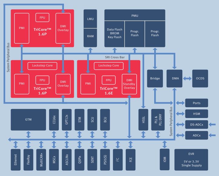
Source: Infineon
All 3 Cores have own RAM, which is organized in so called Scratchpad-RAMs. Each core has a Program-Scratchpad-RAM (PSPR) as well as a Data-Scratchpad-RAM (DSPR) which is accessible through the PMI/DMI (MI=Memory Interface). While Core 0 has 24k of PSPR and 112k of DSPR, Core 1 and 2 have 32k of PSPR and 12k of DSPR. There also is global/shared RAM available in the LMU (Local Memory Unit, 32k). The PMU (Program Memory Unit, up to 4MB) is the flash. But be aware! Every RAM is accessible from everywhere by default. That means that e.g. CPU2 can easily mess around in the RAM of CPU0! Luckily the device has some features to assign certain resources to specific cores.
The peripherals are like on a single core microcontroller. However, shared resources like the peripherals need to be handled with care as concurrent access could lead to unexpected behavior or corrupted data. Therefore, you should (in a hobbyist environment) always try to only access a peripheral from one core. As this is a controller for safety-critical applications, it is equipped with tons of interesting features and peripherals to ensure the integrity of the system. Writing about them would go beyond the scope of this article but you can read a paper I have written about some of the mechanisms if you are interested in this topic (download Functional Safety on Multicore Microcontrollers for Industrial Applications ).
If you want to get started with (AURIX) Multicore, you can go for different Kits. There is e.g. the “ShieldBuddy TC275” from Hitex which is Arduino Shield compatible or for an application Kit with TFT and a few other features. There is a free eclipse-based GCC toolchain available, which also includes debugging software, you can find it at http://free-entry-toolchain.hightec-rt.com/.
How to write multicore software?
As mentioned before, we have only one global ROM which is shared by all cores. If you do not reconfigure the start-address of the cores, all cores start from the same address in the ROM and hence run the same code (at least during the startup-phase).
Execution starts with the “main”-function, right? No.
Actually a few things have to be done before the “main”-function is called. If you, for example, have a variable which is initialized to a certain value, this value needs to be copied from the ROM to the RAM during startup. This and other tasks are performed by the startup-code which calls the “main”-function once the CPU and the memory of this CPU are ready to go.
Every core has a unique ID which can be called by the executing CPU. All Cores start with the same “main”-function, in which you can use e.g. a switch-statement to distinguish between the cores. This means, that you have the same code for all cores but decide in software what shall be executed by which core. Typically, only CPU0 is started after reset and is initializing the peripherals and starts the other cores. However, there are toolchains where each CPU has own code-files and each CPU has its own entry-point, but I prefer the shared code because I think it’s easier to handle and avoids unintended redundancy.
If you work on a single core micro, you usually do not care where variables are linked to. Linking is the process of assigning physical addresses to variables and code. On multicore micro’s this is different, as the linker does not know which core is accessing a certain variable and of course you want that a variable, that is only used on a certain core, is placed in a RAM that is close to this core. First thing to notice is that there are global and local addresses for RAM. A global address (Page 0x5, 0x6 and 0x7 on the TC27x) refers to the RAM of a certain CPU, while local addresses (Page 0xd on the TC27x) refers the own RAM of a CPU. If you link a variable to a global address, it is only available in the RAM of one CPU while if you link it to a local address, it is available in all CPU-RAMs.
But how to assign variables or code to certain addresses? There is a so called “Linker Description”-File which is defining where to put so called “Sections” in memory. This is something you usually do not care about on single-core microcontrollers. Go and check one of your recent embedded-projects, you will very likely find a “.ld” file in your project folder along with a “.map” file in which you can see where code and variables have been linked if the build succeeded. In the code you have to wrap the variable or the code you want to link to a certain location in pragma-directives/sections (at least for GCC) and in the linker file you define where this sections shall be linked.
Conclusion
Multicore microcontrollers require a deeper understanding of how a computer works and how code is assembled into something like a “executable”. Multicore runtime-environments are still in their infancy but will likely reduce the complexity in the future. Actually embedded multicore is a big challenge for the industry too:
It is estimated that multicore technology will increase development expenses drastically. The costs are expected to be increased by a factor of 4.5 while the personal needs is expected to be increased by the factor 3.
(Next Generation Embedded Hardware Architectures, VDC, 2010).
Lack of engineering expertise in efficiently developing, or identifying problems within software to be deployed over multicore/processor architectures remains perhaps
the most critical factor inhibiting the successful migration to new processing architectures.
(Next Generation Embedded Hardware Architectures, VDC, 2010).
This is your chance to get into this topic! Experts in this area are highly demanded!