State machines are everywhere, from a simple edge detection to washing machines to CPUs. The State Machines we will talk about have a finite amount of states those are called Finite-State-Machines (FSM).
We directly start with a small State machine (I skip all the talking about washing machines and stuff, just read through this and you will get the idea).
Lets assume we want to detect a rising edge of a signal. Just in the clock period where the input changed from 0 to 1, the output should be high.
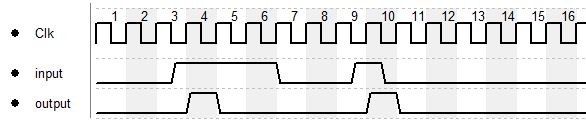
You may notice that there is a delay between input and output, the reason is that the input is checked on the rising edge of the clock and if there was a change from 0 to 1 the output will be set to 1 for 1 cycle.
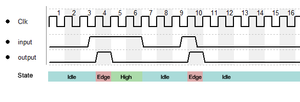
From the diagram above we can extract our 3 states which are the following:
- idle (input is low, we are idling around
- edge detected (input changed from 0 to 1)
- input high (input is at 1 and not changing)
The timing diagram now can also be seen like this:
So we simply need to assign the output to the “edge detected” state and we are done, but before we do so, we go a bit more into the theory, first of all we introduce state diagrams.
State Diagrams
Due to the simplicity of the state machine and because I don’t want to to mess up the diagrams the variable names are skipped in the diagrams, for more complex state machines they have to be added next to the input and output.
The diagrams have the following elements:
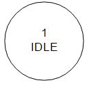
State
Every state has a unique number, this number also has to be in the state symbol, followed by the name
Unfortunately there is no real standard for those diagrams, there are different ways on how to indicate the output of a state, I want to show 2:
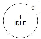
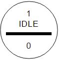
both show the same, in this state the output is 0.
Transition
The step of going from one state to the other is called transition. Every transitions comes with a condition, in our very simple example this is the input.

We can see that if the input is 1 we change to state 2.
So the whole diagram now can be drawn, every state should have 2 transitions, one for every possible state of the input:
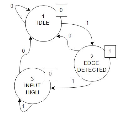
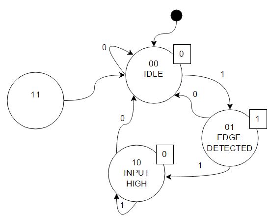
As we want to work in the digital domain we need to change the state numbers into something machine readable. There are different approaches, like gray code or “1 hot” but we want to keep it simple so we just use normal binary numbers.
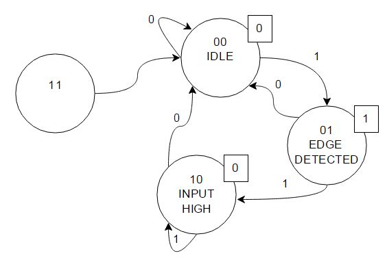
The reason I added the state “11” is that with 2 bits we have 4 possible states. Due to an error it might happen we end up in state “11” and boom… we are trapped. So it is good practice to add all possible states to the diagram to add the possibility to recover from an error. It might be possible that one edge is lost but this is still better than losing the complete functionality. It also is good practice to add an entry point so we know the initial state after startup:
Great, so we have everything, lets bring it into hardware!
From that point on we already could implement the state machine using a switch case which would look like this:
(I added a reset input to force the FSM to the initial state and I had to rename the pins as “input” and “output” are reserved keywords.)
module fsm_v1(
	input wire clk, in, reset,
	output reg out
);

// Declare state register
reg [1:0] state;

// Declare states
parameter IDLE = 2'b00, EDGE_DETECT = 2'b01, INPUT_HIGH = 2'b10, ILLEGAL = 2'b11;


// Determine the next state
always@(posedge clk or posedge reset) begin
	if(reset)
		state <= IDLE;
	else
		case(state)
			IDLE: 			if(in) state <= EDGE_DETECT; else state <= IDLE;
			EDGE_DETECT: 	if(in) state <= INPUT_HIGH; else state <= IDLE;
			INPUT_HIGH: 	if(in) state <= INPUT_HIGH; else state <= IDLE;
			ILLEGAL: 		state <= IDLE;
			//alternative we can skip the "ILLEGAL" state and add a default case
		endcase
end

// Output depends only on the state
always@(state) begin
case(state)
	IDLE: 			out = 1'b0;
	EDGE_DETECT: 	out = 1'b1;
	INPUT_HIGH: 	out = 1'b0;
	ILLEGAL: 		out = 1'b0;
	//alternative we can skip the "ILLEGAL" state and add a default case
endcase
end

endmodule
Simulation is giving what we expected:
![]()
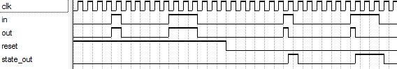
We can dig a bit deeper and observe the internal state which gives us:
![]()
To access the internal register we need to add a wire and assign the register to the wire:
output wire [1:0] state_out
assign state_out = state;
Going for real hardware
The way described above is how you would implement in software, if we talk about hardware we need to simplify the structure, this will also make the implementation in HDL more efficient.
First we need the truth table of the circuit which is having the following structure:
| input | S1 | S0 | S1* | S0* | output | |
We split the bits of the State into S1 and S0.
S1* and S0* describe the state that is followed by the condition on the left side. For now the output depends on the current state.
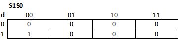
Ok, lets fill that table!
| input | S1 | S0 | S1* | S0* | output | |
| 0 | 0 | 0 | 0 | 0 | 0 | |
| 0 | 0 | 1 | 0 | 0 | 1 | |
| 0 | 1 | 0 | 0 | 0 | 0 | |
| 0 | 1 | 1 | 0 | 0 | 0 | |
| 1 | 0 | 0 | 0 | 1 | 0 | |
| 1 | 0 | 1 | 1 | 0 | 1 | |
| 1 | 1 | 0 | 1 | 0 | 0 | |
| 1 | 1 | 1 | 0 | 0 | 0 |
Based on this truth table we can set up logical conditions for the output variables.
I will use KV-Diagrams to get the required equations (d is the input):
For S0*
Therefore:
S0*=d AND (NOT S1 AND NOT S0)
For S1*
Therefore:
S1*=d AND (S1 XOR S0)
For output
Therefore:
output=(NOT S1) AND S0
With some simplifications the hardware now could look like this:
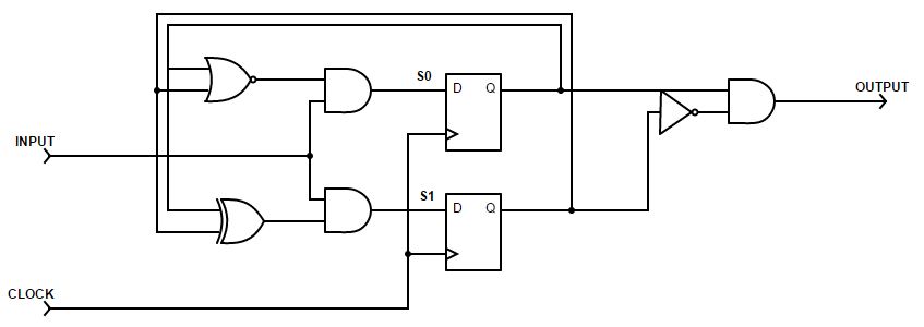
In Verilog we can write:
module fsm_v2(
	input wire clk, in, reset,
	output wire out
);
reg[1:0] state;
parameter IDLE = 2'b00, EDGE_DETECT = 2'b01, INPUT_HIGH = 2'b10, ILLEGAL = 2'b11;

always@(posedge clk or posedge reset)
if(reset)
	state <= IDLE;
else
	//--------######### S1 #########,######### S0 ##########
	state <= {in&(state[1]^state[0]),in&~(state[0]|state[1])};

//output
assign out = ~state[1]&state[0];

endmodule
Simulation
![]()
and with observation of the internal states:
![]()
Mealy and Moore Machines
The way of how to implement a State Machine that was shown above was a Moore Machine. There are different ways on how to implement a State Machine, which one to use depends on the task and the requirements.
However, Moore and Mealy State Machines are the most common ones. The difference is that Moore based machines create the output based on the current state. Each state has a defined output (as we did above).
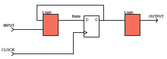
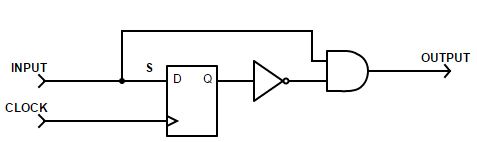
Mealy State Machines build the output based on the current state AND the current input. This also has the effect that the output becomes asynchronous, if you want to make it synchronous, you will have to add a Flipflop to the output signal :
The Edge detection as Mealy Machine
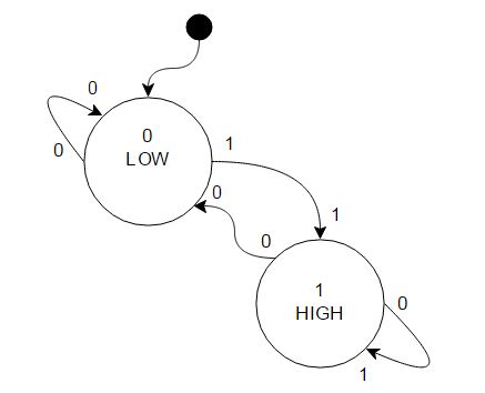
Now that the theory is known, the edge detection can be implemented as a Mealy machine, first thing that may be noticed is that now there is no more direct assignment of the output to the state but to the transitions! The transitions now determine the output, therefore we only have to states, the input is high or the input is low. The number at the tip of the error is the input, the number at the end of the arrow (a.k.a. transition) is the output:
The truth table from this diagram is:
| input | S | S* | output | |
| 0 | 0 | 0 | 0 | |
| 0 | 1 | 0 | 0 | |
| 1 | 0 | 1 | 1 | |
| 1 | 1 | 1 | 0 |
you immediately can see that this is now more compact than the Moore machine.
The Result can be directly seen from the Table:
S*=input
output=input AND NOT S
The result therefore looks like this:
For and simple example like this, the solution above might be the intuitive way, but for more complex requirements its usually not that obvious.
Verilog:
module fsm_v3( input wire clk, in, reset, output wire out ); reg state; parameter LOW = 1'b0, HIGH = 1'b1; always@(posedge clk or posedge reset) if(reset) state <= LOW; else state <= in; //output assign out = ~state∈ endmodule
Simulation:
![]()
With current state:
Excellent post, Thomas, this is what I needed to get me started with the LUT component for the PSoCs. Hopefully you can keep working on the blog, you have some very interesting content here!