In this project I have build a smart power supply, which is providing various voltage domains for a research prototype I work on at my university (Hochschule Darmstadt [h_da]). This prototype is a demonstrator for our multicore ECU runtime environment, that might be used in safety critical applications. In order to spread the safety concept across the whole demonstrator, we need a power supply that is capable to reach a safe state of the system if required. Switching of the power supply is the last line of defense against system errors, though in the given application it is the easiest. We also want to test if multicore microcontrollers can be used to implement fail operational architecture and other interesting use cases.
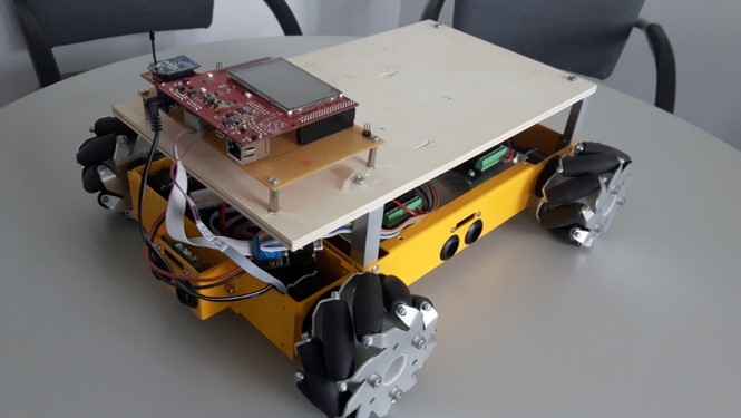
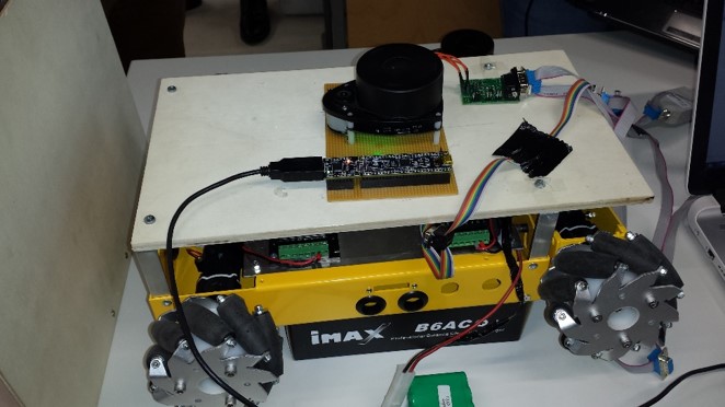
The demonstrator is a mecanum wheel driven car that allows omnidirectional movement and is equipped with a lot of interesting features, such as an LIDAR sensor for collision avoidance and ADAS functionalities. As we are currently building up the system, we are not sure what components will be added or removed and how the final result will look like. A multicore ECU and a smart power supply will be on board for sure.
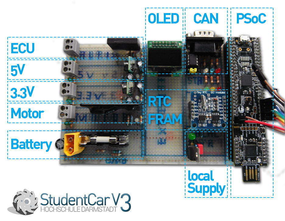
Overview SmartPower Hardware
The SmartPower module connects the onboard battery of the car with all other modules. It continuously measures all voltages and currents and is capable of disabling individual voltage domains. The voltage domains are:
- Battery
- local supply
- ECU
- 5V
- 3.3V
- Motor
Battery and local supply are non controllable domains, though it could make sense to make them controllable in case of some catastrophic situation. Due to the costs of required components and to keep the physical complexity low, I decided that the power supply itself can be seen as trusted (if equipped with a fuse), while all other domains are non trusted and controllable. For the local power supply I decided to use a simple linear voltage regulator, as I thought it is sufficient. Im not sure if this was the right decision, because the power consumption went higher than expected. The simplicity of linear regulators is their benefit as well as their drawback as they get really hot if you draw too much current. A heat spreader can help. ECU and Motor domains are driven directly with battery voltage using photoMOS relais (expensive stuff), while I use step down converters for the 5V and 3.3V domains.
The demonstrator mainly uses CAN for communication between the modules. On top of CAN we use the CANopen protocol, for which I wrote a client and server stack. As the power supply will be the first module to become alive after a reset and maybe is the last module that survives a system-crash, it makes sense to implement some critical features like system-time and synchronization on it. The power supply is therefore equipped with a CAN transceiver and connector, an RTC module. FRAM EEPROM (interesting stuff, check it out) for parameter storage, USB-Logging interface, an OLED to display states, voltages and currents and a lot of LEDs to indicate the status of the power supply (and of course to make it blinky 😉 ). Maybe other components, like an SD card holder, will be added in the future.
Why the PSoC is an interesting choice
Maybe you already figured it out, I am a Cypress PSoC fanboy. This is mainly because it allows rapid prototyping due to its flexibility. For this project 2 features became very useful, the Power Monitor Component and the possibility to build own logic in the CPLD part of the PSoC.
The PowerMonitor is a component from the Cypress component catalog. Features:
- Interfaces to up to 32 DC-DC power converters
- Measures power converter output voltages and load currents using a DelSig-ADC
- Monitors the health of the power converters generating warnings and faults based on user-defined thresholds
- Support for measuring other auxiliary voltages in the system
Support 3.3V and 5V chip power supply
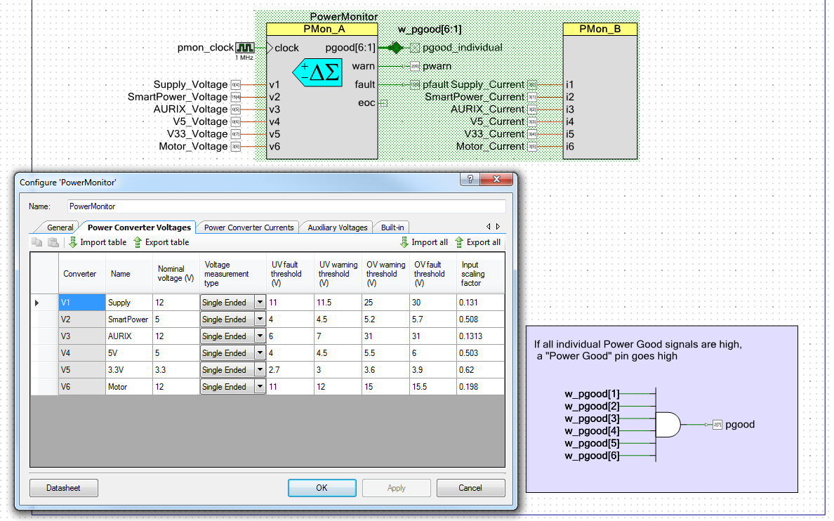
Simply add the component to your design, specify the number and names of the power converters/outputs. Adjust warning and fault thresholds and you are basically done. In this design I use simple voltage dividers (Resistors) to get the output voltage and shunt-resistors with an amplifier will be used for current sensing (still waiting for the parts from china).
I use the programmable logic to implement emergency stop and watchdog functionalities. All the controllable outputs are only enabled if the emergency stop pin has a “high” level. All safety relevant modules on the demonstrator will be connected to a wire which ,at its end, is pulled up by a resistor. If any module detects a critical safety error, it can pull the plug by pulling the voltage level to “low”. If you plan to implement such an mechanism on your own, always make sure that all pins are set to low drive open drain, to avoid that some pin is keeping the level high. For the watchdogs I added 2 counters to the design, which have to be reset periodically. One of the watchdogs is triggered internally to make sure the power supply is still alive, the other one is triggered from the main ECU.
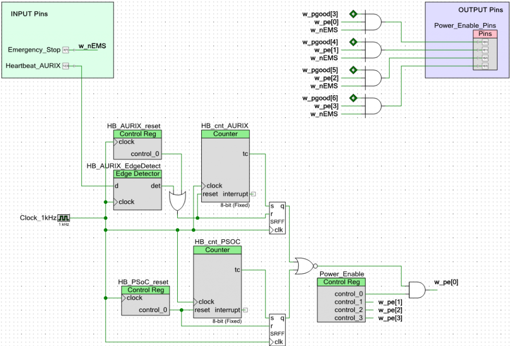
Outputs are enabled using a control register. This is a component which you can control from software. In order to activate an output, you need to disable the faults from the Power Monitor for the converter you want to activate (faults in a converter will set the w_good signal low) and to set the corresponding bit in the control register. If you want to shut down a converter, either there is an emergency stop, the Power Monitor reports a fault condition or the control reg goes low.
Overview Software
With the given complexity and realtime requirements, its hard to implement the software bare metal. I therefore installed FreeRTOS on the PSoC. Of course I used the example project as a starting point but I think it was kind of annoying if you have to start with a full blown project where you do not need most of the stuff. So, if you want to publish some own projects, its nice to have a complex example but please also provide a minimalistic one.
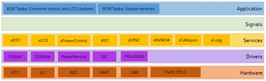
To be honest, I haven’t had too much experience with operating systems on embedded devices. That was one of the reasons why I decided to over engineer this project a little. I wanted to try a few things, learn about the benefits, drawbacks and pitfalls. Now that I gained some experience I am not really sure if I want to go back to bare metal programming. This is also because I build (at least I think so) a quite good base system, which is abstracting the hardware in a generous way and which I very likely will use over and over again. The basic idea behind this is to atomize modules and put them into various layers. Below you can see the majority of modules I wrote for the power supply. The signallayer is not used by now.
Signalflow
I will take the RTC as an example. The Application might request the current date and time. It will call the vRTC service to get this information. The vRTC module is providing an interface to the PSoC internal RTC component. This internal RTC will loose date and time if the system is switched off, therefore I added an external RTC. During startup the internal RTC will be synced with the external one. vSYNC knows the states of all services and in this case also if the RTC is synchronized. vRTC provides a function to request the external date and time from the DS1307 driver(external RTC chip). The DS1307 driver requests a I2C transfer from the vI2C module, which is communicating with the I2C hardware. Of course there might be various I2C requests at the same time. Therefore vI2C uses a message-queue to process one request after the other. Now things start to get tricky. I implemented 3 options placing such asynchronous requests:
Wait for the request to complete. This is usually a bad idea, because you loose a lot of time where you could do other things. If you put a pizza in the oven, you usually do not wait all the time in front of it…. okay… okay… I’ve done it, you’ve done it but you get the idea.
Using handlers. In this approach, the user is proving memory, in which the transfer status is stored. This is nice, because the user can check the status whenever it is suitable, although this can create overhead because you might need to check the status several times.
My favorite is to use callback functions, as there is no busy waiting or polling overhead. In the example above, vI2C is calling a function within vRTC, which was passed by vRTC if the communication with the external RTC failed or succeeded. vRTC needs to check the state of transfer and then can accept the data. This approach has the disadvantage, that the callback function is called within the context of vI2C. If you do not use MPU or similar mechanisms this will work but its kind of messy. But there is another problem with callback functions. If you do not want to write a callback function for every type of request (which you usually don’t…). How do you know which request caused the callback? In order to provide information about the transfer, I implemented something like a delivery note. This is a structure, that is used internally to control external communication and will be passed to the callback function. Below is an example from the vI2C service:
/**
 * \brief I2C message structure
 */
struct vI2C_msg_t{
    uint8_t                 slaveAddress;       /**< \brief I2C receiver address */
    uint8_t*                p_data;             /**< \brief pointer to message */
    uint32_t                cnt;                /**< \brief message length in bytes*/
    uint32_t                transfered;         /**< \brief number of bytes that are already transfered */
    vI2C_flags_t            flags;              /**< \brief message flags*/
    vI2C_speed_t            speed;              /**< \brief desired speed rate */
    transmission_state_t    state;              /**< \brief transmission state */
    void (*p_callback)(vI2C_msg_t);              /**< \brief callback function in case of complete or error*/
    void*                   p_usr_data;         /**< \brief pointer to user data */
};
As you can see, there is a member for user data, if you want to pass additional information to the callback function.