Digital Architectures are digital circuits that implement an algorithm in hardware.
We have different representation forms for digital architectures.
Circuit Schematics
Gates, functional blocks, wires etc. can be used in the design stage and for maintenance as they provide a good overview.
Boolean algebra
Describe the behavior in a mathematical way
Truth Table
Comparison of input and output bits.
Timing Diagrams
Those Diagrams are used to show various signals over the time.
HDL
Hardware description languages are used to describe architecture in a software-like fashion. Besides the text-entry most of the tools also provide schematic entry.
Design Flow
If we want to design a architecture we of course need to know the function we want to implement.
Based on that function we need to decide how many bits are going in and how many bits are going out. With this knowledge we can set up a truth table.
Based on the truth table we can decide which logic-elements we need to implement the functionality. We do so by checking which input combination leads to a 1 at an output.
Example 1: Factorial
In mathematics, the factorial of a non-negative integer n, denoted by n!, is the product of all positive integers less than or equal to n. For example:
$$5!=5*4*3*2*1=120$$
We want to restrict the functionality to only give the factorial upon n=3. We can easily set up a table describing our desired functionality.
| n | n! |
| 0 | 1 |
| 1 | 1 |
| 2 | 2 |
| 3 | 6 |
Pinout
As we are dealing with digital architectures we need to make that binary. First we need to decide how many input/output bits we need.
n will have a maximum of “3” so 2 bits are needed.
n! will have a maximum of “6” so 3 bits are needed.
Hint
If you want to calculate how many bits you need for a certain integer $$\frac{log(“yourinteger”)}{log(2)}$$ and round the result to the next integer. This is the amount of bits you need.
From that we can already see that we will end up with something like this:
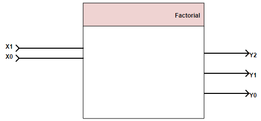
X1 and X0 representing the input bits whereas Y2-Y0 represent the output bits.
The box above is just describing the pinout of our architecture, now we need to specify what is happening inside.
We can translate our function into a truth table, the decimal values usually are not used within a truth table, I just added them to make life a little easier.
| X1 | X0 | X decimal | Y2 | Y1 | Y0 | Y decimal |
| 0 | 0 | 0 | 0 | 0 | 1 | 1 |
| 0 | 1 | 1 | 0 | 0 | 1 | 1 |
| 1 | 0 | 2 | 0 | 1 | 0 | 2 |
| 1 | 1 | 3 | 1 | 1 | 0 | 6 |
Y2
Now we look up which input combination leads to a certain output. Let’s start with Y2 we just look at the case where Y2 is 1.
| X1 | X0 | Y2 |
| 0 | 0 | 0 |
| 0 | 1 | 0 |
| 1 | 0 | 0 |
| 1 | 1 | 1 |
We can see that Y2 is only 1 if X1 AND X2 are 1.
In Boolean algebra we say $$Y2=X1\wedge X0$$
Y1
| X1 | X0 | Y1 |
| 0 | 0 | 0 |
| 0 | 1 | 0 |
| 1 | 0 | 1 |
| 1 | 1 | 1 |
Y1 is 1 if X1 is 1
Boolean algebra:$$Y1=X1$$
Y0
| X1 | X0 | Y1 |
| 0 | 0 | 1 |
| 0 | 1 | 1 |
| 1 | 0 | 0 |
| 1 | 1 | 0 |
Y0 is 1 if X1 is 0
Boolean algebra: $$Y0=\overline{X1} $$
Bringing it together
We now have the Boolean equations:
$$Y2=X1\wedge X0$$
$$Y1=X1$$
$$Y0=\overline{X1} $$
Which directly can be mapped to hardware:
