
I had to interface motor-controllers with CAN, CANopen to be specific. The Name CANopen suggests that this is some kind of open standard with tons of free Stacks and documentation, right? No, not at all.
I had a hard time implementing a own CANopen-Stack on a PSoC 5LP. I want to change these circumstances by summarizing the things I have learned about CANopen, including low-level information. Obviously I can not cover all the features and mechanisms, but the most important ones so you get an idea on how it works.
Index
CAN (Controller Area Network)
CANopen is a protocol based on CAN. CAN is a bus standard mainly designed to be used in vehicles but also in industrial applications or hacker projects 😉 When comparing with the Open Systems Interconnection (OSI) model, CANopen is covering all the layers from Application (7) to Network (3), while CAN is covering the Data Link (2) and Physical (1) Layer. This means that CAN is transporting data on a low level, while CANopen is utilizing CAN and therefore shares the physical restrictions of CAN.
CAN is a serial bus and message-based protocol, which means that every participant of the network (so called Node) can read every message. There is no physical routing between single Nodes.
Every node that wants to receive CAN Messages needs to have at least 1 “mailbox“. There are 2 types of mailboxes, Basic- and Full-CAN mailboxes. The difference is that Basic Mailboxes receive every Message-ID on the bus and the application has to decide if the message is accepted or not, while Full-CAN mailboxes are linked to a specific Message-ID (or range if filtering is available) and only accept this ID(or range) and hence reduce the effort to decide whether a message is accepted or not. The mailboxes are part of the CAN-Logic inside of e.g. a micro-controller and are usually implemented in silicon.
CAN works with 2 physical lines, CAN-HI and CAN-LO. The voltage difference between CAN-Hi and CAN-Lo determines if a logical 0 or 1 is on the bus. The logical 0 is called dominant, as it overwrites the logical 1 which is called recessive. In order to receive and send CAN-Messages a CAN-Transceiver is required, which is converting the differential signal and is implementing a driver. This CAN-transceiver is usually an external IC like the MCP2050 or the TJA1050.
Every CAN message has the same format. (Check Wikipedia for detailed information on CAN. )
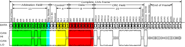
The dominant behavior of the logical 0 is utilized to implement arbitration mechanisms. Nodes are only allowed to send a frame if the bus is free and every node that is writing to the bus is listening to it at the same time. Every CAN frame starts with the arbitration field, that is also acting as message-identifier. If 2+ nodes start to send a CAN frame at the same time, the node with the lower message-ID will win. As soon as as a node tries to write a recessive logical 1 but is reading a dominant logical 0, it knows that there is another node which tries to send a message with higher priority and will abort the message transmission.
In the Control field we have 2 bits that define if this is a remote frame and if the extended format shall be used. The remote frame (RTR) can be used to read out the content of mailboxes without any involvement of the remote node. This has the drawback that it is unknown if this information is still valid and thus RTR frames shall not be used with CANopen. The second bit determines the if this is frame is using the standard (11bit) message-ID or the extended (29bit)message-ID. The extended message-id is only allowed for a few CANopen services and is thus neglected in this introduction. The other 4 bits are the so called DLC (data length code) which determine the length of the frame in bytes.
The data-field can hold between 0 and 8 bytes, determined by the DLC. It is followed by the CRC field that is checked by the CAN-Hardware. Visible to the application are usually only the message-ID, the DLC and the data-bytes.
CANopen
All the data-entities of a node, which shall be accessible through the network, are organized in a object dictionary(OD) where the data is addressed with an 16-bit index and a 8-bit sub-index. There are standards like CAN in Automation (CiA) that standardize the organization of objects to allow manufacturer independent replacement of nodes. The structure of objects is well documented and can be easily found online.
CANopen is providing several services to access data in the object dictionary, control the network and synchronize processes. CANopen identifies each node with a unique node-ID and assign certain message-IDs (called COB-IDs), that depend on the service and node-ID. The node-ID can be between 1 and 127 which means that 127 nodes can be in one CANopen network. The most important services are:
SDO (Service Data Object)
The SDO service can be used to access any object in the object dictionary. Every SDO transfer requires information where to find the desired object in the object dictionary ([sub]index). The SDO service of a node is linked to COB-ID 0x600+Node-ID for accepting frames (RSDO) and 0x580+Node-ID for sending messages(TSDO).
PDO (Process Data Object)
PDOs are linked to certain objects in the object dictionary, this linking is usually freely configurable. When accessing a PDO, there is no need to pass information about the ([sub]index) in the object dictionary and thus the transmission is faster compared to SDO. The COB-ID for R/TPDOs can be freely configured but there are default values.
RPDO= (PDO-Nr*2+1)<<7 + Node-ID
TPDO= (PDO-Nr*2+2)<<7 + Node-ID
SYNC
PDOs can be send in a event-driven or cyclic way. If they are send cyclically, they are synchronized with the SYNC service. It can be configured if a PDO shall be send on every n-th event where n is a value between 1 and 240, where “n” is a value in the OD. SYNC messages use COB-ID 0x80 by default.
There are other modes available.
If n=0 the PDO is send on every SYNC, but only if there is new data available (as the most prominent use-case). n=254 or 255 will send a PDO asynchronus if an event like refresh of the linked object or NMT state-change occures. n=252 and 253 shall not be used, as the require RTR.
TIME
The Time service provides the current date and time to the network. Time messages use COB-ID 0x100h by default.
EMERGENCY
Emergency messages are used to provide critical status information about a node if this node detected an internal error. The Node-ID will be added to 0x80 to create the COB-ID and contains a standardized error-code. The error-codes can be found online.
NMT (Network Management)
An internal state-machine is defining which services are available. There are 4 states: Initialization, Pre-operational, Operational and Stopped. The NMT services is available at COB-ID 0x700+Node-ID.
| Service | Initialization | Pre-Operational | Operational | Stopped |
| SDO | no | yes | yes | no |
| PDO | no | no | yes | no |
| SYNC | no | yes | yes | no |
| TIME | no | yes | yes | no |
| EMCY | no | yes | yes | no |
| ERROR | no | yes | yes | yes |
| NMT | no | yes | yes | yes |
The NMT service is meant to influence this state-machine. After initialization, the state machine automatically goes into the “pre-operational” state.The NMT service has to set the state machine into the “operational” state to make PDOs available. If the Node detects an error, it might go into the “stopped” state, where no access to the object dictionary is possible. The stopped state can be recovered to the “pre-operational” or “operational” state via the NMT.
Diving into the low level
SDO
The most important service from my perspective is the SDO service, which is occupying 2 COB-IDs:
- T(ransmit)SDO 0x580+Node-ID
- R(eceive)SDO 0x600+NodeID
Those COB-IDs are used if the node acts as a server. The RSDO is receiving the request and answers with a response via the TSDO. The terms request and response are always chosen from the point of view of the server. The SDO service is utilizing CAN messages with a fixed DLC of 8 bytes.
CANopen supports 3 ways to read and write data. Normal(segmented), expedited and block-transfer.
Read (upload) request
For normal and expedited transfer, the client sends a request frame to the server:
| byte | 0 | 1 | 2 | 3 | 4..7 | |
| bits | 7..5 | 4..0 | 7..0 | 7..0 | 7..0 | |
| Desc: | css=2 | 0 | IL | IH | s | 0 |
The bits 7..5 of byte 0 are used as function description. In the example above the css (client command specifier) is 2, which means that we want to initiate a upload(read) access. The bits 4..0 of byte 0 are not used and shall be set to 0. Bytes 1..3 are used to address the object in the OD with 2 bytes for the index(IL and IH) and 1 byte for the sub-index (s). If index 0x1337, subindex 0xaa shall be accessed, the frame would look like this:
| DLC | d0 | d1 | d2 | d3 | d4 | d5 | d6 | d7 |
| 8 | 0x40 | 0x37 | 0x13 | 0xaa | 0 | 0 | 0 | 0 |
It depends on the object-size/length if the response of the server is can be transferred in expedited mode (max 4bytes/32bit) or normal/segmented mode (max. 65KiB).
Expedited Transfer
First lets have a look at the expedited transfer, as it is much easier. If the object is smaller/equal 4 byte, it fits into one response message and thus only requires one CAN frame.
| byte | 0 | 1..3 | 4..7 | ||||
| bits | 7..5 | 4 | 3..2 | 1 | 0 | 7..0 | |
| Desc: | scs=2 | 0 | n | e | s | IL|IH|s | data |
Bits 7..5 of byte 0 define the function, in this case the scs (server command specifier) is 2, to indicate a initiate upload response.
Bit 4 of byte 0 is always 0.
The bits 3..2 indicate the number of bytes that are NOT valid. If we transfer 4 bytes, 0 bytes are not valid (the full frame is utilized), if we transfer 1byte, 3 bytes are invalid.
The index/subindex information is passed in the same bytes as in the request (and therefore allows assignment to a request). Bytes 4..7 contain the requested data, starting with the first(lowest) data-byte in byte 4 and the last(highest) data-byte in byte 7.
Bit 1 in byte 0 indicates the transfer mode (0:normal, 1: expedited). As the response fits in one CAN-Frame, expedited mode is used and this bit is 1.
Bit 0 in byte 0 is the size indicator (0: size not indicated, 1: size indicated). In this example the size shall be given and hence this bit is 1.
If the object 0x1337, 0xaa had the value 0xaffe (length 2byte/16bit), the response would look like this:
| DLC | d0 | d1 | d2 | d3 | d4 | d5 | d6 | d7 |
| 8 | 0x4b | 0x37 | 0x13 | 0xaa | 0xfe | 0xaf | 0 | 0 |
Normal/Segmented Transfer
If the object is too big to fit in one CAN-frame the normal/segmented mode needs to be used to transfer the requested data. The response of the server looks like this:
| byte | 0 | 1..3 | 4..7 | ||||
| bits | 7..5 | 4 | 3..2 | 1 | 0 | ||
| Desc: | scs=2 | 0 | n | e | s | IL|IH|s | length |
Bits 7..5 of byte 0 indicate that this is an upload response.
Bit 4 of byte 0 is always 0.
Bit 3..2 which stored the length in expedited transfer mode are unused in this case as the length information is stored in byte 4(LSB) to 7(MSB).
This is a a normal transfer, hence e (bit 1 of byte 0) is 0 (1 would be expedited).
The data size is indicated, hence s (bit 0 of byte0) is 1.
As you can see, the e and s bit combinations determine the mode in which the server wants to respond. The following combinations are possible:
| e | s | Mode |
| 0 | 0 | reserved |
| 0 | 1 | normale mode, length in byte4(L) and byte 7(H) |
| 1 | 1 | expedited mode, length in bit 3..2 of byte 0 |
| 1 | 0 | expedited mode with no length (will not be discussed) |
Lets assume the client wants to read object 0x1338 (subindex 0x0) and this object is 10 byte long. The object shall have the value 0xd0d1d2d3d4d5d6d7d8d9. The server would response with
| DLC | d0 | d1 | d2 | d3 | d4 | d5 | d6 | d7 |
| 8 | 0x41 | 0x38 | 0x13 | 0x00 | 0xa | 0 | 0 | 0x0 |
Byte 0 indicates that the server want to use normal/segmented mode for object 0x1338, subindex 0. The object has a length of 0xa=10d. Byte 5 and 6 are unused and 0.
The Client now has to acknowledge that he want to receive 10bytes in normal mode. The format for the client segment requests looks like this:
| byte | 0 | 1..7 | ||
| bits | 7..5 | 4 | 3..0 | |
| Desc: | css=3 | t | ||
Bits 7..5 of byte 0 define the command, in this case the value 3 indicates a upload segment request.
Bit 4 of byte 0 is a toggle bit that alternates for every subsequent segment. It starts with 0 and is equal for request and response messages.
All the other bits/bytes are not uses and shall be 0.
The first client segment request would look like this:
| DLC | d0 | d1 | d2 | d3 | d4 | d5 | d6 | d7 |
| 8 | 0x60 | 0 | 0 | 0 | 0 | 0 | 0 | 0 |
The server answers with the first segment which has the following format:
| byte | 0 | 1..7 | |||
| bits | 7..5 | 4 | 3..1 | 0 | |
| Desc: | css=0 | t | n | c | data |
Bits 7..5 of byte 0 indicate that this is a upload segment response.
Bit 4 of byte 0 is the toggle-bit that has to be the same as in the segment request.
Bits 3..1 of byte 0 indicates how many bytes do not contain data, if 7 bytes (max) are send, n has the value 0, if only 1 byte is send, n has the value 6.
Bit 0 of byte 0 indicates if this was the last segment or if more segments need to be uploaded (0 more segments, 1 no more segments).
In our example (object 0x1338 with length 10), the first server segment would look like this:
| DLC | d0 | d1 | d2 | d3 | d4 | d5 | d6 | d7 |
| 8 | 0x0 | 0xd0 | 0xd1 | 0xd2 | 0xd3 | 0xd4 | 0xd5 | 0xd6 |
The client now receives the data and is requesting the next segment (note that the toggle bit has changed):
| DLC | d0 | d1 | d2 | d3 | d4 | d5 | d6 | d7 |
| 8 | 0x70 | 0 | 0 | 0 | 0 | 0 | 0 | 0 |
The server now sends the last segment with the remaining 3 bytes.
| DLC | d0 | d1 | d2 | d3 | d4 | d5 | d6 | d7 |
| 8 | 0x19 | 0xd7 | 0xd8 | 0xd9 | 0 | 0 | 0 | 0 |
Note that the toggle bit has changed, c is set and n is set to 4.
Write(download) request
The write request is very similar to the read/upload request. But here the client is choosing which transfer mode is used as the client is providing data to be written.
Expedited transfer
| byte | 0 | 1..3 | 4..7 | ||||
| bits | 7..5 | 4 | 3..2 | 1 | 0 | ||
| Desc: | ccs=1 | 0 | n | e | s | IL|IH|s | data |
Bits 7..5 in byte 0 specify are set to 1 and define a “initiate download request”.
Bit 4 of byte 0 is not used and shall be set to 0
Bits 3..2 define ne number of bytes that NOT contain data. This flied is only valid if e and s are both 1, which is true for the expedited transfer.
Bit 1 of byte 0 is set to 1 and defines that this is an expedited transfer (otherwise it would be 0->normal transfer)
Bit 0 of byte 0 is the size indicator and set to 1 because we will give the size in n. (it would be 0 if no size would be given)
Lets assume the Client want to write the value 0x1234 (2 Byte/16 bit) to Object 0x1339 sub-object 0xa1. The message would look like this:
| DLC | d0 | d1 | d2 | d3 | d4 | d5 | d6 | d7 |
| 8 | 0x2b | 0x39 | 0x13 | 0xa1 | 0x34 | 0x12 | 0 | 0 |
If the server is accepting this download, it will answer with the following format
| byte | 0 | 1..3 | 4..7 | |
| bits | 7..5 | 4..0 | ||
| Desc: | scs=3 | 0 | IL|IH|s | 0 |
The SCS is set to 3: Initiate download responce
Bits 4..0 of byte 0 are not used and set to 0.
The (sub)index that has been written is passed back to the client to determine which operation succeeded. Bytes 4 to 7 are unused and set to 0.
All in one this is a short acknowledge from the server to tell the client the operation succeeded. Following the example above, the server would respond with
| DLC | d0 | d1 | d2 | d3 | d4 | d5 | d6 | d7 |
| 8 | 0x60 | 0x39 | 0x13 | 0xa1 | 0 | 0 | 0 | 0 |
to tell that the write/download operation to index 0x1339/0xa1 succeeded.
Abort messages
There are many things that can go wrong during transfer. One of the easier exceptions is that the size the user wants to write to an object does not match the object size. But as the objects in the OD are equipped with attributes such as read/write etc. there are many possible errors. However, if the server or the client detects an error, the current transfer can be aborted.
| byte | 0 | 1..3 | 4..7 | |
| bits | 7..5 | 4..0 | ||
| Desc: | cs=4 | 0 | IL|IH|s | error-code |
Bits 7..5 again contain a command specifier, in the case of an abort message this is a “4”.
Bits 4..0 are not used and shall be set to 0.
Bytes 1..3 contain information about the (sub)Index, so the transfer can be identified.
Bytes 4..7 contain a error-code that is telling why the operation failed. The error-codes can easily be found online.
PDO
PDOs (Process data objects) are objects that are linked to a CAN-Mailbox. Whenever you write data to this specific mailbox, the data will be automatically written into the linked objects. PDOs can also be used to send out data, in this case certain objects are linked to an TX Mailbox and the content of those objects will be send when the TX-PDO is triggered. There are different kinds of PDO triggers as mentioned in the introduction. PDOs have the benefit that the linking between objects and COB-IDs (CAN Message-IDs) is known and thus no index/subindex information need to be passed. Usually 4x2byte Objects are linked to one PDO. The assignment of objects to an RPDO starts on object 0x1600 and 0x1a00 for TPDOs. The configuration of the triggers can be found from index 0x1400 for RPDOs and 0x1800 for TPDOs.
There are several interesting use-cases for PDOs, I want to highlight 2 of them. In the first use-case one node is acquiring data via an ADC. This data shall be passed to 2 motors which are equipped with CANopen-.compatible controllers.
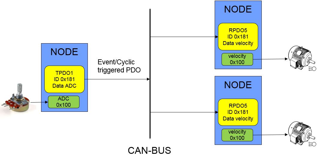
The node that is providing the data is triggered cyclic (via SYNC) or whenever the ADC value is changing. The ADC value is stored in an object and this object is linked to an TX PDO (in this example TPDO1). The receiving nodes both have a RX PDO (in this example RPDO5) that is linked to the target velocity object of the motors. Whenever a CAN-Frame with a matching COB-ID (in this example 0x181) received, the value will be passed to the target velocity.
Another use-case is synchronized reading. Lets assume we have several sensors in the network and we want to have the a snapshot of all values at a given time. Obviously, sequentially asking one sensor after the other would corrupt the snapshot as the timing becomes inconstant. PDOs provide an elegant way to implement such features. As mentioned in the introduction, PDOs can be send cyclically based on the SYNC service (which will be discussed in detail later). If all nodes with sensors are configured to respond to a SYNC with providing the sensor-data, then a real synchronous snapshot is possible. As the nodes can not answer at the same time (shared bus), the nodes internally will create a copy of the desired data and wait for the bus to send data.
SYNC
SYNC messages are triggers to synchronize the behavior of the bus. As explained in the PDO-section, they can be used to synchronously read PDOs. SYNC Messages do not contain data and and have a standardized COB-ID. Usually there is only one node in the network that is producing the SYNC signal. However, as the COB-ID for SYNC messages is configurable on every node, it is possible to create several SYNC-producers and therefore different time-domains.
A default SYNC message has a length(DLC) of 0 byte and is send to COB-ID 0x80.
TIME
This services is providing data/time information and can be used as a global clock in the network. The Time-Message is split in two parts and has a length of 8 byte.
| byte | 0..3 | 4..5 | 6..7 |
| Desc: | Time after midnight | date since 1.1.84 | 0 |
Bytes 0..3 represent the number of milliseconds after midnight (of the current day).
Bytes 4..5 represent the number of days since 1.1.1984
Bytes 6..7 are not used.
NMT
The NMT service is used to influence the NMT-FSM (finite state machine). A NMT message is 2 byte long (DLC=2) and is using COB-ID 0.
| byte | 0 | 1 | 2..7 |
| Desc: | NMT-command | Node-ID | 0 |
Byte 0 is the command to be send to the NMT. The most important commands are:
- 1 start node (pre-op/stopped -> op)
- 2 stop node ([pre]op->stopped)
- 80 enter pre-op (op/stopped->pre-op)
- 81 reset node (x->initialization)
- 82 reset communication (x->initialization)
Byte 1 is addressing the Node-ID that shall be controlled. A 0 in this byte will address all nodes on the bus!