
Modern microcontrollers have advanced memory systems such as SRAM, DRAM and also Flash on chip. Because of the limited write-cycles of Flash and the fact that you usally have to write big chunks of data at once, writing non volatile data to the flash is usually a bad idea.
When I had a more detailed look at my Cypress PSoC 4 BLE Pioneer Kit I found a 1 Mbit FRAM chip (FM24V10). I already heard about FRAM but had no idea how to use it. Therefore I wrote a small driver which makes the FRAM usable.
But wait, what is FRAM?
F-FRAM is for Ferroelectric RAM and works based on a ferroelectric film as dielectric, in which atoms change the polarity under the presence of an electric field. The advantage of FRAM is that it provides a high endurance (up to 100 trillion read/write cycles for the one on the kit) at a high data retention time (151 years for the one on the kit) and is capable of writing data instantaneously with bus-speed. There are chips with serial and parallel interface available, the one on the pioneer kit has a I²C Interface.
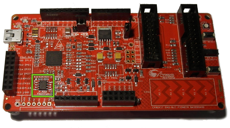
First let’s have a closer look at the pioneer kit and the physical connections of the chip. You find the FRAM chip on the base board of the kit.
Now lets have a look at the schematics which can be found in the Kit guide.
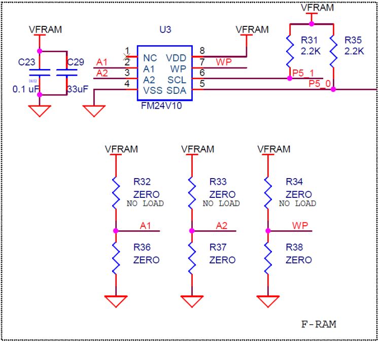
© Cypress Semiconductors
From the Datasheet of the FRAM we can see that pins A1 and A2 determine the I²C Slave address. As they are both pulled down, the resulting slave address is 0x50. By moving the resistors from R32 to R36 and/or R37 to R33 you could change the slave address. Pin WP (write protect) is connected to ground to allow write access to the FRAM, by moving the resistor from R38 to R34 you could make the FRAM write protected.
To talk to the FRAM we now need to create an I²C Instance in a PSoC-Creator workspace and rout the Pins to the corresponding output-pins of the PSoC (5.1 for SCL and 5.0 for SDA as it can be seen from the schematic).
I wrote a basic driver which can be found here and which might help you getting started. The only thing you need to do is to set up the Symbol for the I²C Instance in the header-file (the Name in this example was “I2C”.
#define I2C_INSTANCE I2C
You have to call FRAM_Start() once before using the driver as this call will start the I2C instance.
If you want to extend this basic driver or find any bugs, you are very welcome.